I have been toying with the idea of designing my own circuit boards and this post is about my very first board.
Back in December, I decided to give it a go and design something very simple. It was meant to be more like a training exercise, rather than a board I desperately needed. The board was going to have 3 small potentiometers; by attaching it on an arduino I should be able to get the readings on the serial port.
After looking at all the different software packages, I ended up using FreePCB to design a very simple circuit board. I found that FreePCB was very easy to learn and use. I used BatchPCB (a SparkFun service) to get the card printed:
http://www.batchpcb.com/index.php/Products/26633
The guys at BatchPCB were kind enough to send me two boards (I only ordered one). The order took approx 4 weeks, which is not bad, if you are after the cheapest possible way of getting a board printed. I paid $14, including delivery to London.
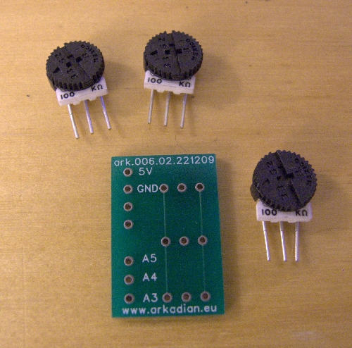
Front side, with the potentiometers. By the way, when I got the board back, I realised that I got the numbering wrong: instead of A5, A4, A3, it should read A0, A1, A2…

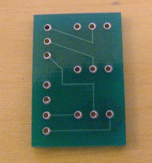
Back

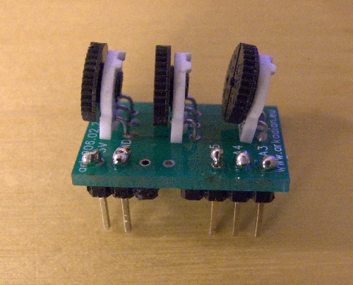
pins and pots soldered in position (I know, I need to work on my soldering skills…)

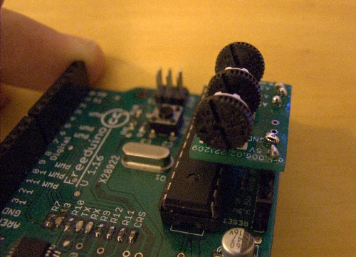
The mini board on a freeduino board

The following Arduino code works nicely for this example:
1 2 3 4 5 6 7 8 9 10 11 12 13 14 15 16 17 18 19 20 21 22 23 24 25 26 27 28 29 | int sensorPin1 = 1; int sensorValue1 = 1; int sensorPin2 = 2; int sensorValue2 = 2; int sensorPin0 = 0; int sensorValue0 = 0; void setup() { Serial.begin(9600); } void loop() { // read the value from the sensor: sensorValue0 = analogRead(sensorPin0); sensorValue1 = analogRead(sensorPin1); sensorValue2 = analogRead(sensorPin2); //print the value on the terminal Serial.print(sensorValue0); Serial.print(" \t "); Serial.print(sensorValue1); Serial.print(" \t "); Serial.print(sensorValue2); Serial.println(""); delay(100); } |
As I said before, this was just a test. Hopefully my next board will be part of a more exciting project!