Robot Challenge 006

Not as productive as I hoped this weekend. I managed to complete the cable harness of the motors and blue leds (which was rather boring but important for the project) and tried out a new look (as I’m moving away from the use of reel cans as my chassis).

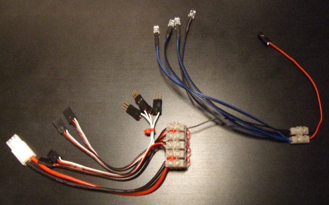
Here is the cable harness, before the insulation tape got applied:cable_harness.

The advantage of this harness is that all the motor cables are neatly hidden away and only 4 cables appear on the top surface (one for each motor), plus one for the blue LEDs and the ground cable.

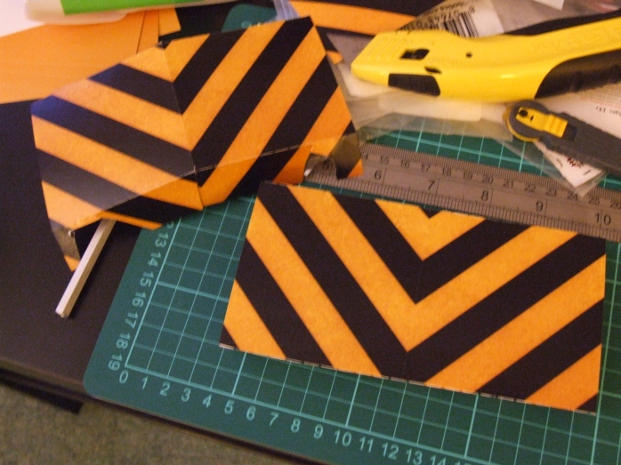
Regarding the new look – I got a few patterns printed on photographic paper and converted them to the side motor panels with a bit of cutting and scoring:
cat_style_corners

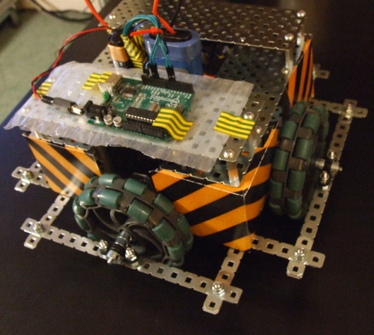
Here is how Arkadian-AV1 looks like at the moment (this is still a temporary look):

latest_arkadian-AV1

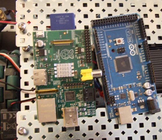
The image shows an old Freeduino I have for testing. The final robot will be using an Arduino Mega for controlling the motors, reading the sensors and lighting the lights, but all the “thinking” will be done by the Raspberry Pi. rpi_ardmega

Here is a little video, where each motor goes forward for a sec, backwards for a sec, then all the leds are turned on and then the same sequence is repeated on another motor.

Robot Challenge 006 from Arkadian.Eu on Vimeo.

Robot Challenge 005

Today I have quite a bit of work to do on this project. By the end of the day, I should have a fully functional remote control vehicle.

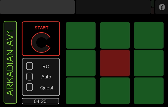
Earlier this morning, I finished the joystick. I will be using a Nexus 7 with touchOSC as my joystick and I put together the following layout:

OSC_Control_Panel

Rotating the “Start” icon to “Full” will wake up the robot.

The three toggle switches underneath will simply be switching between RC mode, Auto mode (just avoiding stuff) and Quest mode (which I will be able to finetune a bit better, for our competition).

The navigation buttons on the right will be doing what you expect: North, East, South, West and their combinations. The red button in the middle will be the stop button.

When the robot is ready, I will add additional pages to the remote control to increase the number of options available to the user (e.g. speech, reactions, specific moves, etc).

There is a great OSC Python library (PyOSC) which makes interfacing the Nexus with python very easy. While OSC was created to control music, you can make it do whatever you want in Python, which is really cool.

By the way, while I’ll be using a Nexus 7 tablet, it’s worth mentioning that TouchOSC works on iPhones and iPads too. Excellent app! 🙂

Robot Challenge 004

The chassis is now more or less operational. Here is a video of it being controlled by an arduino.

Robot Challenge 004 from Arkadian.Eu on Vimeo.

In this example, all wheels get the same movement instructions, but, as the weight of the battery is falling mostly on one wheel, the rotation is not perfect.

In any case, this will be fixed when I have the final balanced chassis and of course the compass module connected and the Raspberry Pi module correcting the movement.

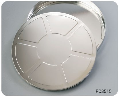
Next week, I’ll focus on the second part of the chassis. I will use film reels from PEC:

35mm_2000ft

I’ll have one for the motor section at the bottom reel, a battery section, a brain (RPi & Arduino) section and a sensor reel at the top. The logitech sphere camera will be sitting at the top, giving it a “Cyclop” look.

I’m also planning on adding a few blue LEDs at the bottom reel, which should give the robot a nice under-body glow.

Vex Motors on Arduino

Vex motors (with the Vex Motor Controller 29) are essentially servos. To use them on an Arduino as motors, all you need to do is figure out the “angles” that give you the right speed.

The problem is that all motors are slightly different. To find the right angles for my motors, I simply modified the “knob” example on the Arduino Aplication (1.0.1) to this:

1
2
3
4
5
6
7
8
9
10
11
12
13
14
15
16
17
18
19
20
21
22
23
24
25
26
27
28
29
#include <Servo.h> 
 
// create servo object to control a servo 
Servo myservo;  
 
// analog pin used to connect the potentiometer
int potpin = 0;  
 
// variable to read the value from the analog pin 
int val; 
 
// vex motor value
int vex;   
 
void setup() 
{ 
  myservo.attach(11); 
  Serial.begin(9600);
} 
 
void loop() 
{ 
  val = analogRead(potpin);            
  vex = map(val, 0, 1023, 0, 179);
 
  myservo.write(vex); 
  Serial.println(String(val) + "  VEX:" + String(vex)); 
  delay(15); 
}

By adjusting the potentiometer a number of “VEX” angle values are generated, from 0 to 180. Make sure that you have the serial monitor up!

My motor was working at the following angles:
20 degrees: move forward
138 degrees: move backward
91 degrees: stop motor

based on the above findings, we can then test the VEX motor by using the following arduino sketch:

1
2
3
4
5
6
7
8
9
10
11
12
13
14
15
16
17
18
19
20
21
22
23
24
25
26
27
28
#include <Servo.h>
Servo Motor; 
 
const int MF = 20;  // angle that moves motor forward
const int MB = 138; // angle that moves motor backward
const int MS = 91; // angle that stops the motor
 
void setup()
{
 // The white pin of the VEX motor controller 29
 // connects to pin 11 (or any other PWM pin)
 Motor.attach(11);
}
 
void loop() 
{
  Motor.write(MF); // move forward
  delay(1000);     
 
  Motor.write(MS); // stop motor
  delay(1000);  
 
  Motor.write(MB); // move backward
  delay(1000);
 
  Motor.write(MS); // stop motor
  delay(1000);   
}

Robot Challenge 003

Today I worked on a few necessary but rather boring parts of the construction.

I got the Sparkfun compass module from Proto-Pic and spent a few hours setting it up and calibrating it.

I used the HMC5883L Arduino library example to generate the following:

1
2
3
4
5
6
7
8
9
10
11
12
13
14
15
16
17
18
19
20
21
22
23
24
25
26
27
28
29
30
31
#include <Wire.h>
#include <HMC5883L.h>
 
HMC5883L compass;
int error = 0;
 
void setup()
{
  Serial.begin(9600);
  Wire.begin(); // Start the I2C interface.
  compass = HMC5883L(); // Construct a new HMC5883 compass.
  error = compass.SetScale(1); // Set the scale of the compass. Was 1.3 in the original
  error = compass.SetMeasurementMode(Measurement_Continuous); 
}
 
// Our main program loop.
void loop()
{
  MagnetometerRaw raw = compass.ReadRawAxis();
  float heading = atan2(raw.YAxis, raw.XAxis);
 
  if(heading < 0)
    heading += 2*PI;
  // Check for wrap due to addition of declination.
  if(heading > 2*PI)
    heading -= 2*PI;
 
  int headingDegrees = int(heading * 180/M_PI); 
  Serial.println("@|"+ String(headingDegrees) + "|#");
 
}

I wasn’t getting the readings I wanted though. I was hoping to get 0 for North, 90 for East, 180 for South and 270 for West, with an offset or something.This is what I was getting: N=330, E=90, S=200 and W=265, which meant that the distances N-E, E-S, S-W, W-N were not 90 and were not equal. Not sure why, but for my project it doesn’t make much difference, given I’ll be using a Raspberry Pi for the brain.

I wrote the following python script for calibrating the arduino results:

1
2
3
4
5
6
7
8
9
10
11
12
13
14
15
16
17
18
19
20
21
22
23
24
25
26
27
28
29
30
31
32
import serial
from time import sleep
 
def xmap(OldValue, OldMin, OldMax, NewMin, NewMax):
	t =  ((OldValue - OldMin) * (NewMax - NewMin))
	t = t / (OldMax - OldMin) + NewMin
	return t
 
 
ser = serial.Serial(2, 9600, timeout=0)
 
data = ""
while True:
	try:
		data = data + ser.read(9999)
		if data.find("@")>-1 and data.find("#")>-1: 
			data = data.strip(' \t\n\r')
			x = data.split("@")[1]
			x = x.split("#")[0]
			x = x.split("|")[1]
			x = (float(x)/10 + 3)%36
 
			if 0<=x<12: y = xmap(x,0,12,0,90)
			if 12<=x<23: y = xmap(x,12,23,90,180)
			if 23<=x<29.4: y = xmap(x,23,29.4,180,270)
			if 29.4<=x<36: y = xmap(x,29.4,36,270,360)
 
			print int(round(y,0))
			data = ""
	except: pass
 
ser.close()

The above script actually gives very acceptable results. If you use it, just ensure you feed the xmap function the information you observe in your compass.

In the final project, the compass module will be detecting the rotation of the robot and report it to the main python script. if the robot has rotated by mistake then the main python script will make the necessary adjustments.

On the battery front: I received the battery I ordered from VEX. Originally I was thinking of using sealed led acid batteries, but I didn’t want to use high voltage on the motors. Tomorrow I’ll time the battery to see how long it lasts when it powers 2 motors together.

I think I’m now ready to build the body of the robot and setup the main Python script on the Raspberry Pi for the RC mode. When that’s all done, I will add the proximity sensors and the autonomous mode on the main Python script.

The plan is also to buy an Arduino Mega, as I will need 8 digital ports for the motors, 2 ports for the compass,
Robot Challenge 002

The project is moving along quite well.

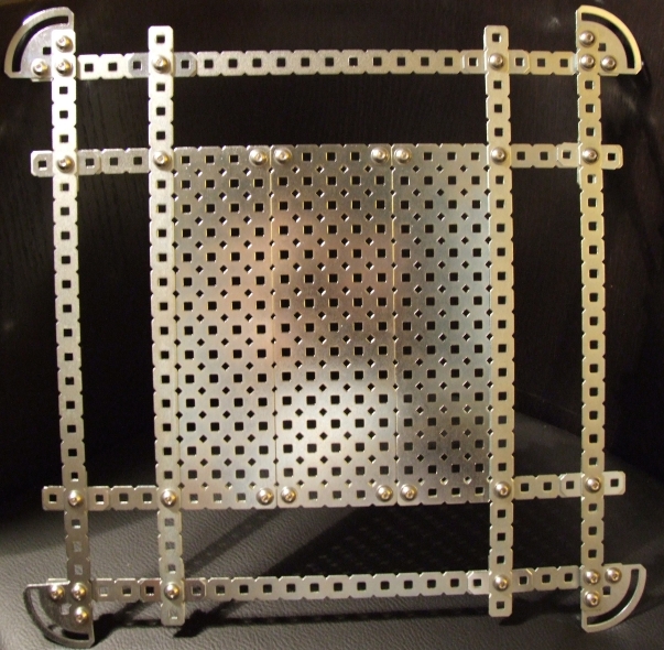
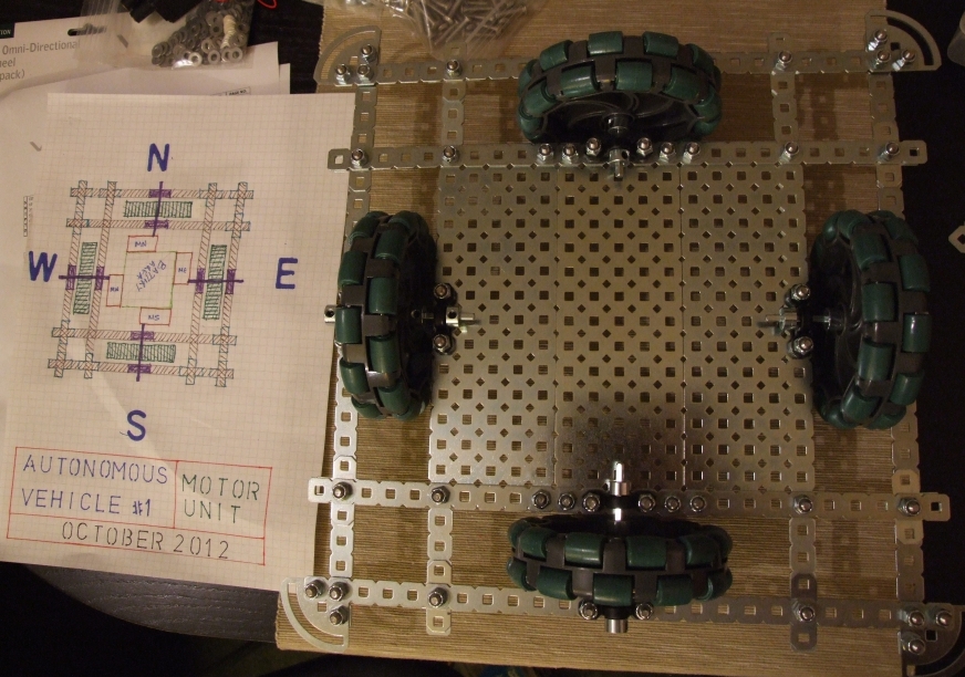
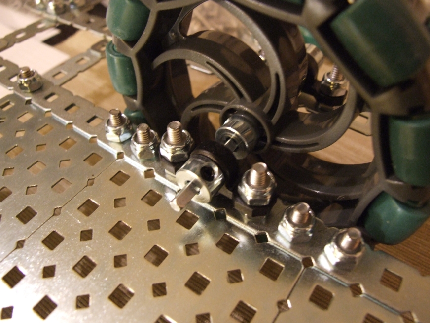
Today I received my second order from VEX Robotics and got a chance to finish the chassis.

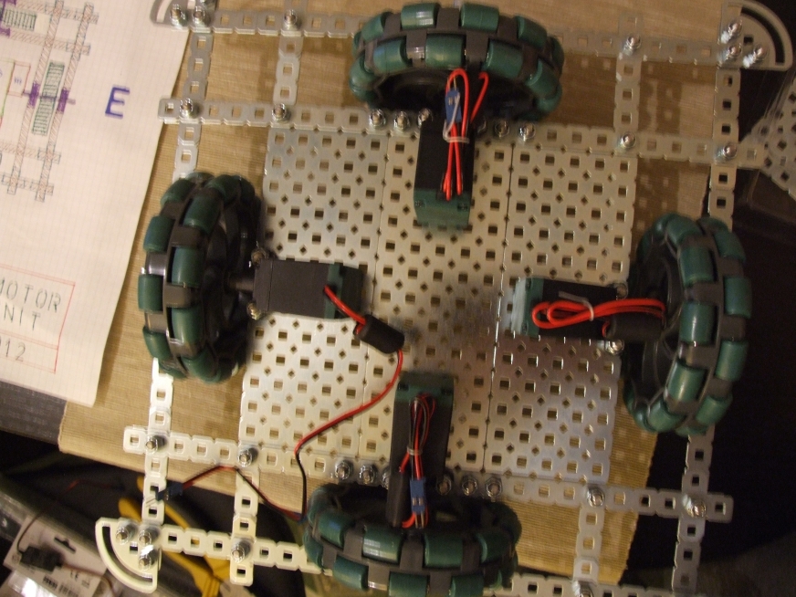
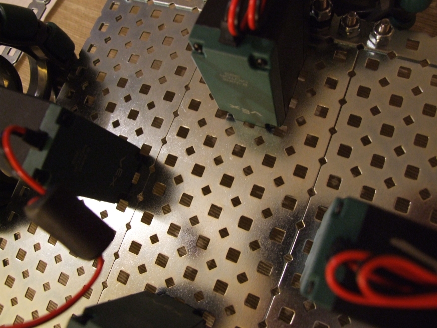
Here are some photos:

chassis_base_only

chassis_with_wheels

chassis_wheel_detail_2

chassis_with_wheels_and_motors

chassis_motors_detail_1

I now need to get a power source for the four motors. I’m thinking of getting a couple of lead-acid batteries at 12V and reduce the voltage output to 9V.

I’m thinking not to use the VEX motor controllers and to use an H-Bridge for each motor (I already have one of these chips). The advantage of this approach is that I can drive each motor with 2 digital outputs directly from the RPi, rather than putting an arduino in the middle. By the way, the H-bridge I linked above allows the use of two motors per pcb, but things will run better if each chip is used in “single motor” mode (more amps available per motor).